Adding Fans
Desigo CC includes a default fan for all geographical guidelines, standards, and technical versions. The default fan is configured to project requirements after adding to the graphic.
- In the Mode group, conduct one of the following actions:
- Click Design
 . Previously rotated objects appear in the default direction.
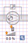
- (Optional) Click Test
 . In this case, the fan is not displayed to scale.
- In System Browser, select logical view.
- Select Logical > [Network name] \...\ [Plant] >
- [FanEx (Extract air fan)]
- [FanSu (Supply air fan)]
- [FanEh (Exhaust air fan)]
- [FanOa (Outside air fan)]
- [FanRc (Recirculating fan)]
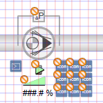
- Drag the object to the graphics page.
- The added object displays at the maximum scale. All elements configured on the symbol are displayed. This ensures that there is no overlapping with a neighboring object during runtime.
Information

NOTE:
Drag-and-drop only works if a Desigo CC function is assigned to the object after data import.
You can check the object data on each symbol.
Rotating
- The fan symbol is added to the graphic.
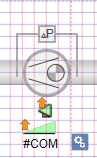
- In the Mode group, click Test .
- The fan symbol displays as per the important data points and default direction
 .
.
- Select the fan symbol.
- Left-click and hold; right-click until the fan symbol is displayed in the desired direction.
- Release the left mouse button.
- The fan symbol
 is displayed in the desired direction.
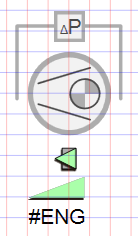
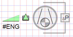
Direct Entry of Direction under Symbol Properties > Substitution > Direction | ||||
Fan Direction | ||||
0 | 1 | 2 | 3 | 4 |
|
|
|
|
|
Information
NOTE:
In drawing mode, the fan is always displayed in the default state.
Changing the Default
- The fan symbol is added to the graphic .
- In the View tab, select Properties.
- The Symbol Properties dialog box is enabled.
- In the Mode group, click Test .
- The fan symbol displays as per the imported data points and the selected direction.
- Select the fan symbol.
- Select Symbol Properties > Substitutions.
- In the Style field, enter a number between 0 and 2 (see Table Define Fan Style).
- Click ENTER or change to another entry field to activate the change.
|
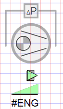
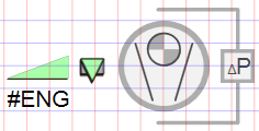
Define Fan Style | ||
DIN | Variants | Swedish/Finnish |
0 | 1 | 2 |
|
|
|


Information
NOTE:
In drawing mode, the fan is always displayed in the default state.